Arduino is a popular microcontroller platform known for its low-cost hardware. Many people use Arduino to build a wide range of small projects. Some of these projects also require a firmware update feature. While Arduino supports self-flashing, that alone is not sufficient. If the latest firmware has issues, a buggy update could potentially break the system. In such cases, the only way to recover the system is to manually reflash a working firmware. To avoid such situations, a firmware rollback feature becomes essential. However, this requires additional hardware to store both the new and old firmware versions.
In this project, I am developing a custom bootloader that can back up the old firmware, flash the new firmware, and verify its functionality. If any issues are detected, the bootloader automatically rolls back to the backed-up firmware, ensuring the platform remains operational.
Hardware Setup:
Since the Arduino Uno, Nano, Pro Mini, and most other models have only 32KB of flash memory, storing both the old and new firmware requires at least 64KB of space. To meet this requirement, I chose the 24LC512 IC, a 64KB external EEPROM.
Typically, 512 bytes of the 32KB flash memory are reserved for the bootloader. However, this space can be adjusted to 1024 bytes, 2048 bytes, or even 4096 bytes using fuse settings. The default 512 bytes is insufficient to support the rollback feature along with other functionalities. Therefore, the fuse settings have been updated to allocate 2048 bytes (2KB) for the bootloader. As a result, the effective space available for the main firmware is reduced from 32KB to 30KB. Consequently, the full 64KB capacity of the external EEPROM is not required to store two firmware versions. This leaves approximately 4KB of free space in the EEPROM, which can be used to store flags across hard or soft resets to retain the platform’s state.
Fuse Setting:
Fuse settings can be modified to unlock certain advanced or hidden features, but doing so can be risky if you’re not fully aware of what you’re changing. Incorrect fuse configurations may render the microcontroller unresponsive or difficult to recover. A useful tool for understanding and editing fuse bits for the ATmega328P is available at this portal: Fuse Calculator for ATmega328P. It provides a clear explanation of each bit in the fuse registers.
This is the fuse configuration I used in this project.
| High Fuse | Low Fuse | Extended Fuse |
| 0xD8 | 0xFF | 0xFF |
To update this configuration, the following command can be used
avrdude -v -C avrdude.conf -p <HW_PART_NUMBER> -c <PROGRAMMER> -P <PORT_NUMBER> -U hfuse:w:0xD8:m -U efuse:w:0xFF:m -U lfuse:w:0xFF:mEEPROM CONNECTION:
The 24LC512 EEPROM uses an I2C interface, allowing communication with the Arduino via its I2C pins. However, I2C is a shared bus, meaning any device connected to it can potentially access the EEPROM. To prevent unintended access by other I2C devices, a transistor-based logic circuit is used to control the EEPROM’s visibility on the bus. This logic is managed through Arduino GPIO pins. The bootloader controls these GPIOs to selectively expose or hide the EEPROM from the I2C bus. Before accessing the EEPROM, the bootloader isolates itself by disconnecting from the shared bus. Once isolated, it safely connects the EEPROM, ensuring that only the bootloader has access. This mechanism prevents other devices on the I2C bus from interacting with the EEPROM.
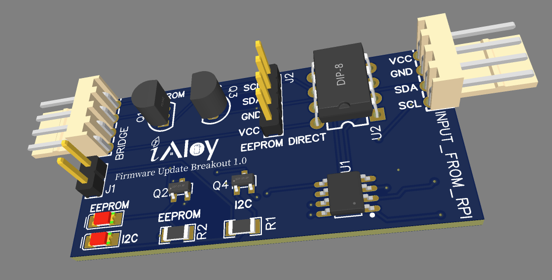
Here is the schematic and PCB layout for reference. fwu_with_24lc512_test_baord
Bootloader Workflow:
Here is the main bootloader code. https://github.com/iAloy/iBootLoader. As the EEPROM has slots to hold two firmwares, we call them Slot 1 and Slot 2.
Firmware Upload:
- A script named
manage_fwu_eeprom.pyis used to upload the new firmware to Firmware Slot 1 in the EEPROM. In addition, it updates the configuration space via the I2C bus. - Once the upload is complete, the Arduino device needs to be reset.
Firmware Update Process:
- On reset, the bootloader reads the configuration space and initiates the firmware update.
- The current working firmware is copied from the Arduino’s flash memory to Firmware Slot 2 in the EEPROM. This is the backup firmware.
- The new firmware from Firmware Slot 1 overwrites the working firmware in the Arduino’s flash memory.
- The configuration space is updated again to reflect the new firmware.
Execution and WDT:
- The bootloader sets the Watchdog Timer (WDT) and jumps to the starting address of the new firmware.
- The firmware is responsible for turning off the WDT during its initialization.
- If the firmware fails to turn off the WDT, the WDT will reset the Arduino.
Rollback Mechanism:
- If the WDT reset occurs, the bootloader assumes the new firmware failed.
- The bootloader will then restore the previous firmware from Firmware Slot 2 in the EEPROM back to the Arduino’s memory.
- The bootloader jumps to the restored firmware to resume normal operation.
Find Other works: https://arghyabiswas.com/projects/
Leave a Reply